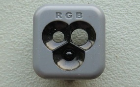
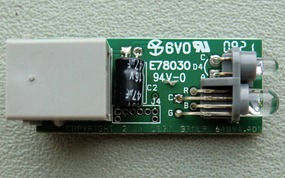
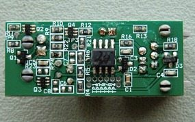
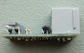
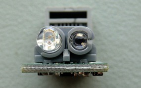
No, not a HiTechnic sensor in this episode of Exposed. Yesterday someone on the Mindboards forums asked what the third bump on the LEGO Colour Sensor was for. I was curious enough to take a small blade to one of my sensors and take it apart. I did take some grainy pictures but figured I could probably get better ones today. So here it is, the LEGO Colour Sensor, exposed in all its glorious nekkidness.
 |
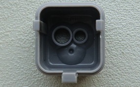 |
| Front view of the sensor cap. Looks pretty fake now, doesn’t it? | You can see that there’s a solid lump of plastic behind the bump. |
If there is a sensor you’d like to see exposed, drop me a note. Make sure you check it’s not one I have done before, though. You can do that by browsing through the Exposed category. Please note that I cannot disassemble Mindsensors sensors, they’re really sandwiched together and it would take a Dremel and a lot of tears to take those apart.
 Bot Bench I'd Rather Be Building Robots




Love it!
That’s actually pretty cool. It’s also kinda a bummer, though. I had assumed they had red, green, and blue LEDs in there, each one shining a light and checking for it’s own frequency range. :/ Oh well, looks like I’ll have to make my own.
I am not sure how you would do that 🙂 You mean each bump is both a sensor and an LED?
– Xander
In theory, does this mean that with special drivers/sensor firmware, you could power any combination of the three colors? Or would you need to change the circuitry inside?
I have no idea what the sensor is capable of. There is no publicly available documentation on its internals.
I imagine it’s hard to search for the chip info when the marker mark is part of it’s ID. How do you type “scratch mark”? 🙂
It’s probably some kind of ATiny chip. 6-outputs. 1 for the phototransistor, 3 for the LED, and 2 for NXT communication.
I think it’s high time one of us took a logic analyzer to this thing, don’t you? LEGO wouldn’t get mad if someone figured this one out, would they? They didn’t before.
Ports. Not all “outputs”, ports.
You could also just check out the Lejos or standard/enhanced 1.28+ firmware source code 🙂
Ohhhh….. _ _
|
—–
Drat. Formatting on previous comment ruined. I think you can guess what it is though. 😉
The Lego Hardware Developer Kit has it. Look in there, there’s a schematic and everything. PDF form. It’s on the Lego Mindstorms site under the files thing in support. Click the advanced tab and find it in there.
Thanks, I’ll check it out.
I’ve just checked the HDK on mindstorms.com, and it’s for the 2006 NXT 1.0. It only contains the schematic of “Light sensor” module. Anyway the other components are still up to date, but the “Color sensor” module is part of the NXT 2.0 set and there is no schematic in the HDK for it.
i would realy like to see the ultrasone sensor beeing exposed ! i am verry curious how that look like when its exposed
I just opened one and it’s very cool 🙂
Hi Xander,
thanks for your work.
Could you give some infos on how you open the sensors without breaking them?
I had a try with the colour sensor once, but I stopped by fear of breaking it.
What kind of tools do you use and where do you put force to avoid breaking them?
Hi there,
Well, to be honest there is no nice way to open these. As you may have noticed when trying to open yours, there are 2 small tabs on the white cover that hook into the gray body. Those tabs can only come out when the front of the body comes off. The front of the body is hooked into the main part by 3 “hooks”, 2 of which are covered by the white thing on the top. So they really made it a one-way assembly. What you could do is pull the side of the white cover and cut as far into the tab as you can so it leaves a tiny little stub. That way the cover kind of stays when you reassemble later. I have spare covers so I don’t usually worry about that too much.
Thanks.
Have a nice day.
The Bump’s purely for a balanced appearance when the sensor is viewed from the front. Things always look better in odd numbered groupings. Apparently we are hard-wired to perceive it….
Thanks for exposing this! I was troubled to know what the third “sensor” slot was for. Now it is clear there is really nothing there. Also, this sensor is written up as doubled into a lamp but really the LED is there mainly to help the sensor I think. The programming objects talk about reading the sensor with or without the LED turned on.
hi
please, i wana use lego color sensor to a microcontroller atmega32, so i have to know the inputs and the output and the algorithm that detect the color
thanx
Hey there,
You will have to dig in the LEGO NXT’s firmware to find out. There is currently no publicly available information about this sensor. You could also take a look at the source code for Lejos.
thanks xander
Will you be exposing any of the EV3 sensors? I would be interested to see those.
I don’t have any EV3 sensor housings to fix them back up right now but I have reached out to LEGO to send me some broken sensors to take apart and put up here 🙂 I’ll keep you posted!
Cool, looking forward to seeing them.