I’ve had my ArduinoMega for almost 2 weeks now and until today I had no luck getting it to work as an I2C slave with the NXT. The NXT is a finicky beast when it comes to I2C. It’s really not all that standard and requires very high pull-ups (82K) for the NXT to be able to pull the lines down properly.
After testing the ArduinoMega’s ability to play I2C master to a number of ICs I had lying around, an MCP23008 and a DS1631, I was pretty sure the I2C lines were working properly. I tried in vain to make the ArduinoMega work as a slave with the NXT using the AVRlib I2C library, the one provided by the Atmel AVR311 Appnote (source code) and the Arduino Wire library. Having tested it with 3 libraries, I was pretty sure it was probably not a software issue but some stupid electrical problem. Little did I know how stupid it turned out to be.
Lacking the proper equipment to further diagnose the problem, namely a scope and a logic analyser, I employed the help of my friend Joep. We hooked up the ArduinoMega to his PC based I2C master board and all tests completed successfully. The board responded as it should so that definitely ruled out the software as a source of our problems. So what could it be? We connected the ArduinoMega to the NXT using a small breadboard and two 82K pull-ups. With the scope hooked up to SCL the problem became pretty obvious; the NXT wasn’t pulling down the line enough. That made no sense, since the internal pull-ups of the ATmega1280 were explicitly disabled in our program. Joep re-examined the PDF with the circuit diagram and discovered that the SDA and SCL lines had in fact 10K pull-ups! They were not drawn near the chip itself, but way, way off in the top right corner where you could easily miss them. With the 10K pull-ups in parallel to the 82K ones, the resulting pull-up resistance had been reduced to a mere 8K9. After a little brain surgery, the two evil pull-ups from Hell, were removed and subsequent testing resulted in a successful NXT to ArduinoMega I2C transaction!
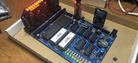
If you plan to use your ArduinoMega with an NXT, you will need to remove R2 and R3, which you can find below. Click on the left picture for a larger version.
Be very careful when removing these two resistor, of course. You don’t want to end up damaging your board. Joep is quite experienced in soldering very small components and has a very fine tipped soldering iron. The end result was very nice. Click on the picture on the right to see a bigger version.
So why had no one else bumped into this problem with Arduino’s before? Well, it turns out that the Arduino Duemilanove, for example, does NOT have these pull-ups. The SCL/SDA lines are shared with the ADC channels. You can’t very well put a pull-up on an ADC channel. I am not sure why they would put the pull-ups on the SDA/SCL lines on the ArduinoMega when they weren’t there on the normal Arduino.
Thank you, Joep, you saved the day!
 Bot Bench I'd Rather Be Building Robots
![[Click to enlarge] [Click to enlarge]](http://mightor.files.wordpress.com/2009/08/arduino_mega_edited_thumb.jpg)
![[Click to enlarge] [Click to enlarge]](http://mightor.files.wordpress.com/2009/08/cimg9585_cropped_thumb.png)


I noted that my new Seeduino Mega also does NOT have pull-up resistors installed for the I2C signals.
http://forum.seeedstudio.com/viewtopic.php?f=4&t=378&sid=b95f2c598895822405484c3a3673ef67
I saw the Seeeduino Mega has quite a number of extra I/O ports as well. Good to know that they didn’t include the extra 10K pull-ups on their version.
I had recently had a problem similar to this. I had a MTRMX-Nx from Mindsensors powered directly from the NXT’s rechargeable battery, which was in my NXT at the time (originally I had 4 AA batteries, but they provided only 4V, then I learned the input voltage: output voltage ratio was 3:2, as confirmed with the ratio 9V:6V). It was a 6-Volt light, but I disconnected it after I discovered a problem. (The light still works.) When everything was powered, and the MTRMX-Nx was connected to an NXT sensor port, I heard a loud, fuse-like noise, and the NXT turned off, with the occasional horizontal line stretched across the screen. After a week or two it was discovered I had accidently reversed the polarity between the battery and MTRMX-Nx. I can now power a fluorescent light (like the kind one might put in a closet) through an NXT brick. Once I’ve finished my project, I will be able to wake up without being temporarily blinded or becoming annoyed with some radio alarm clock.
I´m trying to connect a RTC Mindsensor to arduino Duemilenova but I can´t to read any values from the sensor. I use I2C with pins 4, 5 (analogue inputs).
My conexions are:
White Wire of the RtC sensor: to 5v arduino
Black and red wires to GND arduino
Green to 5 v arduino
Yellow to SCL line(pin 5 arduino)
Blue to SDA line (pin 4)
The code is:
#include “Wire.h”
#define DS1307_I2C_ADDRESS 0xD0 // This is the I2C address
// Global Variables
int i;
byte second, minute, hour, dayOfWeek, dayOfMonth, month, year = 0;
// Convert normal decimal numbers to binary coded decimal
byte decToBcd(byte val)
{
return ( (val/10*16) + (val%10) );
}
// Convert binary coded decimal to normal decimal numbers
byte bcdToDec(byte val)
{
return ( (val/16*10) + (val%16) );
}
// Gets the date and time from the ds1307 and prints result
void getDateDs1307()
{
// Reset the register pointer
Wire.beginTransmission(DS1307_I2C_ADDRESS);
Wire.send(0x00);
Wire.endTransmission();
Wire.requestFrom(DS1307_I2C_ADDRESS, 7);
// A few of these need masks because certain bits are control bits
second = bcdToDec(Wire.receive() & 0x7f);
minute = bcdToDec(Wire.receive());
hour = bcdToDec(Wire.receive() & 0x3f); // Need to change this if 12 hour am/pm
dayOfWeek = bcdToDec(Wire.receive());
dayOfMonth = bcdToDec(Wire.receive());
month = bcdToDec(Wire.receive());
year = bcdToDec(Wire.receive());
Serial.print(hour, DEC);
Serial.print(“:”);
Serial.print(minute, DEC);
Serial.print(“:”);
Serial.print(second, DEC);
Serial.print(” “);
Serial.print(month, DEC);
Serial.print(“/”);
Serial.print(dayOfMonth, DEC);
Serial.print(“/”);
Serial.print(year, DEC);
}
void setup() {
Wire.begin();
Serial.begin(57600);
}
void loop() {
//Serial.print(“ahi van”);
getDateDs1307();
delay(1000);
}
Do you have pull up resistors connected to your SCL and SDA lines? You’ll probably need about 4.7-10K or so.
Regards,
Xander
Thank you, but no run.
I´m not be sure about the pin conections of the rtc mindsensor.
I read the book “extreme NXt” and the autor says this:
PIN 1 (White Wire)= 9v or 5v
PIN 2 and 3 (Black and red wires) = GND
PIN 4 (Green wire) = 4.3 v
PIN 5 (Yellow wire)= SCL
PIN 6 (Blue wire) = SDA
But in the datshhet of the RTC mindsensor say:
I2C Operations
Pins used: SDA(1), GND(2), SCL(3), +5V(4)
Ok! the programs runs. My prblem was that the RTC address specified in the datasheet is 0xD0) but i2c adressing uses the high 7 bits so it’s 0x68.
Thak you!!!
Hi,
I’m doing exactly the same using an Arduino Mega 2560, who has the same 10k pull-ups, but in this case they can’t be removed because they are in a pic with a third resistance which controls the reset of the board. How i can manage this? Thanks a lot!
I am not really sure, to be honest. Perhaps you can figure out which of the legs are for SDA and SCL and cut those? You risk damaging your Arduino, though.
Thanks, but i don’t think this is possible, or it will be very difficult. But i’m still studing where is the problem, and i’m not sure that the pull-up resistors are really needed. I’ve been trying to communicate Arduino Duemilanove and the Mindstorms without any pull-up resistors, and everything works fine. So, why it doesn’t work with Arduino MEGA? If i solve this problem i will post-it here for everybody who are interested 🙂 And if someone wants to help we can speak by mail. Thanks again!
Thank you Xander.
Once again you have saved us!
Like you, we have been trying to get the NXT to talk I2C to the Arduino Mega 2560 (ours is R3) and it works with other devices, etc., but on the oscilloscope we saw that signal was not pulled down as far as we expected and from the current measurements, we concluded the pullup must only be about 8K, not the 20K to 50K as in the atmel datasheet, but looking at the schematic we did not notice the additional external pullups because they aren’t connected via lines.
On the R3 board, they are in RN1 (Resister Network 1) and they are on the middle 2 pins of that part (which has 4 10K resisters in one package), and as far as I can tell by looking at the pads and by searching the .pdf of the schematic for “RN1”, the top and bottom resisters in the network are not used for anything.
RN1 is in the same general area as the 2 discrete resisters you have circled in your picture (of the older revision of this board).
We removed the whole thing and it seems to still be working, but we aren’t using anything other than I2C (aka TWI) right now, so if those other resisters really are needed for something, it might bite us later. They don’t seem to be.
One really puzzling puzzle, when we just “read the pin” values, we were able to see the NXT signal in the Arduino firmware. That led us to think the signal was “low enough” even though not all the way to 0V, but after removing the resister network, TWI/I2C actually WORKS with the NXT!
We think this is because the signal path to the “read pin” is different than the signal path to the “SCL INPUT” (the former goes through a schmitt trigger and a synchronizer), so maybe that is why you can get the right value from the port, but the TWI interface doesn’t see it.
(fwiw, the I2C spec says the “low” signal needs to be 0.3*V where V is the bus voltage, 4.3 or 5 in this case. Thus, it should be less than 1.5V to be “sure”, and ours was a little more than 2V when “off”, so clearly outside the acceptable spec, even though “almost working”).
Again, Thank you for this post.
Just confirming:
On the Rev 3 Arduino Mega 2560 R3 “A” and “D” pins (1,8,4,5) of the Resister Network RN1 are not connected to anything (according to the board and schematic files on the Hardware page of the Arduino web site (which I opened with Eagle Lite version 6)).
Therefore, it is safe to completely remove RN1 rather than try to saw it apart or whatever. We tried several techniques, and the easiest for us was a pair of Weller tweezers, held upside down to heat all 8 pins at the same time.
Can you put a link to the both example code (NXT and arduino) ?
I don’t really have any. I wrote this article 5 years ago 🙂 I am pretty sure there are lots of examples of how to connect your NXT to an Arduino. This article was simply for the pull-up resistors.
= Xander