 Bot Bench I'd Rather Be Building Robots
Some people have mailed me asking if it was a light sensor. Well, yes, it’s a sensor that uses light, but that’s far too generic an answer to accept.
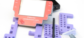
I’ve been working on the Mystery Project and it’s currently not working yet. I’ve probably made a mistake on the prototyping board. Here’s a picture of its current state.

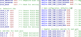
It doesn’t seem to be doing much at the moment, but this is pretty much how it’ll be in the end (minus the bugs). I’ve probably made a small mistake putting the components into the board. It’s black and white for a reason. It would be way too easy to duplicate this thing on your own breadboard if you knew which values go where but this will get you the basic shape of it. You should be able to guess what’s ground and what’s V+. I’ve not tried to trick you, simply because in doing so I’d probably mess it up for myself, too.
So no generic guesses. I need to know what it is and what it’s for.


It think I see the problem. In the B&W picture, you have nothing connected to the base of the transistor. I think you want to move that resistor to the base, therefore having the transistor act like an amplifier, Vs. doing nothing.
There is a resistor connected to it, you just can’t see it properly in the picture. I just verified on the actual prototyping board. I think I have a resistor or cap connected to the wrong thing in there somewhere.
Then is the picture “outdated”? It is very clear that only two of the transistor pins are connected (1 and 3), and one of them has both the jumper wire and resistor connected. Being that is IS correct, it is then likely that the picture is just a previous one (not up to date). I am unsure of the schematic that you used, and therefore I am not able to recognize any other potential problems. I hope you get this working soon. It sure is an interesting sensor.