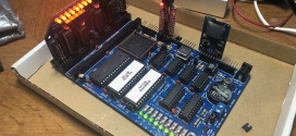
 Using a pot meter to test the MAX127 is not a hugely useful way to exploit the power of this ADC. Instead, this time I have replaced the pot meter with an IR receiver. The main part of this circuit is still exactly the same as in the previous MAX127 post. The only difference this time is the IR receiver, IR LED and the astable oscillator circuit with the 555 IC. The oscillator has been configured at 36KHz, which just so happens to be the frequency at which the TSOP2236 is most sensitive. Coincidence? I think not!
 I took the basic 555 circuit from here. I modified a little to make it work with my IR LED and oscillate at 36KHz with as close to a 50% duty cycle as I could get it. After running some calculations I picked a 1K and a 1.5K Ohm resistor in combination with a 0.01uF capacitor to give me the right frequency with a duty cycle of roughly 38%, close enough for me. The mathematical details can be found on the page with the original 555 circuit. Below you will find a table of components.
| R1, R2 | 82 KOhm |
| R3, R4, R5, R7 | 1 KOhm |
| R6 | 1.5 KOhm |
| C1 | 4.7 uF |
| C2, C6, C7 | 0.01 uF |
| C3, C4, C5 | 0.1 uF |
| D1 | Red LED 10mA |
| D2 | IR LED |
| 555 | 555 IC |
| TSOP2236 | TSOP2236 IR Receiver 36KHz |
I used the same program as in my previous article about the MAX127. However, now it was pretty clear what kind of readings I could expect from such a sensor. With no obstacle between the sensor and the LED, I would get a reading of 0 or 1. With no IR light hitting the sensor, the MAX127 would return a reading of around 1620. Due to the nature of my setup, I could only configure the LED and sensor to be facing each other head on. I leave it as an exercise for the reader to configure the breadboard in a slightly better way so it can be used as a proper distance measuring circuit.
You will need to calibrate the sensors of course, the values 978 or 1300 are pretty meaningless if you don’t know what distances they represent. Also keep in mind that IR distance gauging is very dependant on the amount of light reflected by the surface you’re measuring against. That means that if you’re measuring against a nice smooth white surface you will get a different reading from measurements at the same distance against a black velvety surface (for example). The white surface is nice and reflective, whereas the black velvet surface will absorb a great deal of the light.
Happy distance gauging!
 Bot Bench I'd Rather Be Building Robots


[…] Filed under: Experiments, Sensors — Xander @ 08:57 In two previous articles (here and here) I had tried to come up with a way to use IR light to gauge distances. It wasn’t […]