 Bot Bench I'd Rather Be Building Robots
Here’s the first release of the HiTechnic Prototype Board driver for RobotC. It has all the basic functionality you’ll need to use it.
- byte HTPBReadIO(tSensors _link, byte _mask)
- Returns values of inputs specified by mask
- void HTPBWriteIO(tSensors _link, byte _mask)
- Writes values to outputs specified by mask
- void HTPBSetupIO(tSensors _link, byte _mask)
- Configure the ports for input or output according to the mask, 0 = input, 1 = output
- int HTPBReadADC(tSensors _link, byte _channel, byte _width)
- Read the value of the analogue channel specified. For more or less accuracy you can specify either 10 or 8 bits as the width.
You can pick up the code for version 0.2 here: LINK (Version, 0.3 available here). This code has only been tested with RobotC 1.40 Public RC2. The next version of the HTPB driver will allow you to change the update interval for the input values.


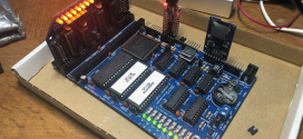
The demo code in it works with the breadboard setup above. Note that it is exactly the same as on the HiTechnic Prototype Board page, apart from the LED colours. R1-R6 are 470 Ohm resistors and R7 is a 1K Ohm pot meter. D1-D6 are standard LEDs.
How does it work? As you turn the knob on the pot meter, you change the voltage on the analogue input. The small IC on the proto board changes this into a digital value that is sent to the NXT. The NXT switches the LEDs on or off, depending on the value of the analogue input. This is all done through the same proto board.