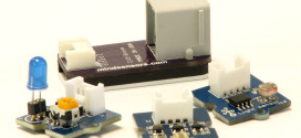
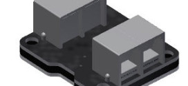
 A few weeks ago I was lucky enough to receive one of the main components in the upcoming Renewable Energy Add-on Set.
I didn’t get a manual with it so it was a bit of a mystery to me. However, thanks to John Hansen and some very helpful peeps at the Lego Electronics R&D department I got some more information on what makes this thing tick.
It’s an I2C controlled sensor. There are some nice blocks for it available right here: [LINK] (thanks to Jetro for pointing that out to me). John Hansen is busy working on the NXC drivers for it, so expect it to work on that platform very shortly. I’m going to be working on the ROBOTC support for this little gem.
So what does it do? It can measure the amount of voltage, current and total wattage produced –and- consumed by what you hook up to it. It has a small LCD matrix screen that displays all the current stats. You can recharge the removable battery using your NXT’s motor ports. I am sure you’re dying to know what’s inside this thing? I know I was, so I took a screwdriver to it.
 |
 |
 |
| Main unit with detachable NiMH battery. | First level of disassembly. | The main board, top side. The small daughter board attached by cable is the top PF connector. |
The green button switches the unit on. The orange switch has three positions, 0, left and right. It has a Technic axle hole in it, so you could connect something to it. The idea is that you input energy via the bottom input and once you have more than 1 Joule of energy stored in this unit, you can use the orange button to control the output connector on the top. You could run a little light on it, a motor, whatever you’d like.
If you’re keen to write your own driver for it, here’s a list of all the registers:
| Register Name | Number | Register Name | Number |
| Voltage In, LSB | 0x0A | Voltage In, MSB | 0x0B |
| Current In, LSB | 0x0C | Current In, MSB | 0x0D |
| Voltage Out, LSB | 0x0E | Voltage Out, MSB | 0x0F |
| Current out, LSB | 0x10 | Current out, MSB | 0x11 |
| Joule, LSB | 0x12 | Joule, MSB | 0x13 |
| Watt in, LSB | 0x14 | Watt in, MSB | 0x15 |
| Watt out, LSB | 0x16 | Watt out, MSB | 0x17 |
Requests need to be sent to I2C address 0x04 and all results (apart from Joules) need to be divided by 1000. Also, when you read the values above in one single request, they are latched, in other words, they are a proper snapshot of a single timeframe.
So there you have it. You can expect this sensor to be supported in NXC pretty soon, I’m sure, I won’t make any promises John has to keep, though :) I will be making the ROBOTC driver for this sensor part of the Driver Suite very soon.
 Bot Bench I'd Rather Be Building Robots


Xander thank you for the EMeter breakdown. We have a question – does the EMeter calculate Amps from an input voltage on the input wire or does it also get current on the input wire? We have an experiment with the solar panel and the EMeter stops sending us Amps when the capacitor gets to 100J accumulated. Our experiment needs to run far longer. Right now we are calculating Watts and Joules on our own from the EMeter’s reported Volts and Amps, but when it gets to 100J it stops sending Amps although it still sends Volts. We know how to calculate Amps from Volts but do not know what value of resistance to use – could you possibly help? We suspect the EMeter only receives voltage levels on the input wire and is calculating Amps. THanks in advance!
Mike,
I am not familiar with the EMeter’s internals, other than what you can see from visual inspection. I didn’t get any internal documentation, everything I know about its I2C interface, I gleaned from software written by John Hansen. Perhaps you could ask the people at LEGO Education?