 Bot Bench I'd Rather Be Building Robots
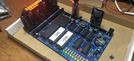
Next Saturday (21 July 2008 ) I am giving a presentation on the Parallax Propeller microcontroller and I thought it would be a nice idea to demo some things with it. I have a Propeller Education Kit (PEK) and a Propeller Proto Board (PPB), kindly donated to me by Parallax. The PEK is awesome for learning how to use the Propeller as it comes complete with a veritable mountain of components, including the chip itself, of course and a very big breadboard. The PPB is great because it allows you to hook it up to any monitor using the accessory kit that comes with a VGA and 2xPS2 connectors.
From my days with the BoE Bot I remembered a lesson that taught a way to gauge the distance to an object using an IR sensor and LED. On a microcontroller without an Analogue-to-Digital Converter (DAC) built in this would only allow the a simple “object detected” and “no object detected’ state. That is not very useful in a real environment. The IR detectors are quite tricky little things. Most of them are sensitive only to a very limited wavelength of light, usually somewhere in the 950nm range. However, in order for them to be less influenced by regular light, especially fluorescent light, they are made to be sensitive only to light that hits them at a certain frequency. This frequency depends on the sensor make and model and usually is set to anywhere between 32KHz to 40KHz.
The frequency sweep method
 This bring us to the first method of object detection. Although the sensor is made to detect incoming IR signals at 36KHz, that does not mean it can’t detect signals at other frequencies. It can and will detect them, just not as well. We can exploit this property by varying the frequency we make the LED flash at. I used the TSOP2236 that is preset for, you guessed it, 36KHz. As can be seen from the graph to the left, the response is not quite linear, but it’s as close as it’s going to get. If we take 36KHz as our base frequency and sweep as high as 1.2 x base frequency then our top frequency will be 43.2KHz. We will ignore everything on the left side of the bell curve.
 So how does it work? A non-optimal frequency makes the sensor a little more short-sighted. The less optimal the incoming signal is, the more short sighted the sensor will appear to be. We take the frequency range between 36 and 43.2KHz and chop it up into 100Hz parts. That gives us 73 possible readings. Instead of writing a whole bunch of code myself, I took the code from the PEK bot project on the Parallax site and modified it a little to make it a bit more flexible.
  I set up the circuit on the PEK and took readings from 5 to 30 cm in 5 cm intervals. There are no absolute frequency values, just frequency index numbers. In order to reduce the noise, I averaged 10 readings at each distance and repeated the experiment 3 times. The graph is pretty much what I expected; a somewhat non-linear response to the incoming frequency. It is a nice way to be able to tell roughly how close an object appears to be, rather than the binary “object detected”/”no object detected”. However, can we devise a better method?
Variable Resistance Method
 This method does not depend on sweeping the incoming frequency to make the sensor short sighted. Instead we will merely reduce the amount of light the LED will emit at the base frequency. This method was discussed at the Stamps In Class forums. The project uses preset resistors set up in a parallel configuration, allowing for a wide variety of combinations resulting a large range of different resistances. One of the readers of the post suggested using a digital pot meter, in other words a DAC to vary the resistance. I picked up one of these DACs, an MCP41010, that has a range of 0 to 10KOhm with an 8bit resolution, giving it 256 steps. I picked it because it has an easy to use SPI interface.
 Programming the code for the pot meter wasn’t terribly difficult in hind-sight but this was the first time I had used SPI. I managed to find some code that used SPI for some other device, I modified it to use the commands described in the MCP41010 datasheet. I was pleasantly surprised how easy it was to get working. To the right is the layout of the circuit I used. The controller has been left out for clarity. The tests were done by starting the MCP41010 in its maximum setting and slowly decreasing the resistance in steps of 5. I think going through each possible setting would’ve been overkill and this still gives us 52 steps.
 The results were, well, a little less than overwhelming, to be honest. The curve is very similar to the previous one. For the amount of extra circuitry and code you don’t get a whole lot more performance. It was a fun experiment and perhaps there are some things you could do to improve this circuit. If you have any suggestions, please leave a comment.
Testing methods
 The experiments were done with both circuits on the same PEK at the same time. This allowed me to test both circuits under the exact same circumstances. I secured the breadboard in place with some tape and drew lines at 5 cm intervals from the front of the PEK. I used a large non-IR transparent object (read: wooden box). I made sure the object was perpendicular to the sensors at all times. The button on the right side of the board is the trigger. Each time it is pressed, the first sensor is tested 10 times followed by the second sensor. This allows me to move the object without getting any readings.
Above right is a picture of the breadboard with everything on it. I hope you enjoyed this article as much as I enjoyed doing the experiment.
You can find the code for this project here: LINK.


Great Article! I hope to build my own soon!! 🙂
good article for build robot 🙂
[…] Filed under: Experiments, Sensors — Xander @ 08:57 In two previous articles (here and here) I had tried to come up with a way to use IR light to gauge distances. It wasn’t very […]